(No. la)
SPECIAL INSTRUCTIONS FOR BUILDING MECCANO SUPER MODELS
Meccano Motor Chassis
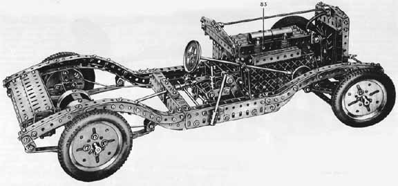
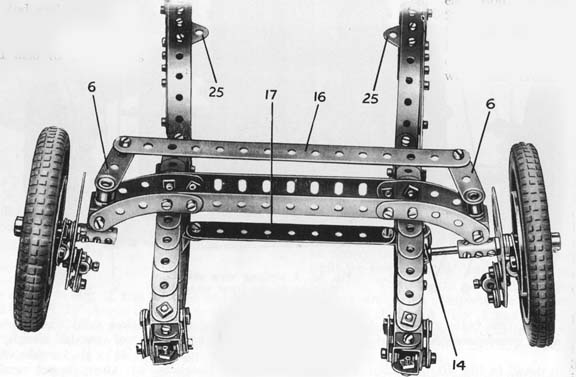
Fig. 1.General View of the Chassis
Built with Meccano Outfit L Special Features :— Four-speed forward and reverse gear-box; differential gear; single plate clutch ; four-wheel internal expanding brakes with hand and foot control; underslung axles ; Ackermann steering, etc. |
The illustrations
to this leaflet show the model built in Blue-Gold Meccano parts. Its
construction in the Red-Green Meccano parts is exactly the same.
The motor unit, an El Electric Motor, is placed, together with the clutch and gear-box, in the position occupied by the engine in the actual car. In this manner the appearance of the model is kept as close to that of the original as possible. The brakes, which in actual practice are controlled by rods, are controlled in the model by bowden cables, as this form of construction makes the model simpler to build.
Page.1
The Prototype
The Meccano model is, as far as possible, a replica of the new Bentley chassis that is now being manufactured by the makers of the Rolls-Royce cars. This car is fitted with a 31/2litre six-cylinder engine, having a nominal cylinder capacity of 3,669 c.c. The complete power unit is flexibly mounted in the chassis at the rear on two rubber pads, and at the front on a flexible beam fitted with a shock absorber.
The gear-box is of the four-speed forward and reverse type, the drive being taken from this through a substantial open propeller shaft. It is interesting to note that neither torque rods nor torque tube are fitted, the entire driving strain being taken up by the rear springs. Each of the four wheels is fitted with a large diameter internal expanding brake, operated through a disc clutch-type mechanical servo motor mounted on the gear-box. All brakes are compensated relative to each other, a hand adjustment being provided for the front pedal brake.
The performance ol this car is remarkably high although this can be really appreciated only when driving on roads where some of the 120 b.h.p. may be unleashed in safety. On the revolution counter, which is scaled up to 5,000 r.p.m., a red mark has been introduced at 4,500 r.p.m., this being considered the desirable limit speed of the engine. This engine speed gives a road speed of 94
m.p.h., when travelling in top, and when in third gear the speed is about 75 m.p.h. Similarly, second gear gives a little over 54 m.p.h., and first a little over 34 m.p.h.
The chassis is of deep saction in the centre, tapering considerably to •each upswept end. The springs are all of the half elliptic type, and hydraulic shock absorbers are fitted to each, but on account of their small size these have been omitted in the model.
The Main Frames
One side of the chassis frames is shown in Fig. 3, the forward end being at the right-hand side of the illustration. A 71/2" Angle Girder 1 is attached to a 51/2" Angle Girder by means of a 51/2" Flat Girder as shown. The rear end of this complete member carries at its broad side two 2 1/2" large radius Curved Strips, and these are connected together by a bolt at the point 2. This bolt carries also a Flat Bracket that will later form part of the spring suspension link. A 2" Strip is now fitted and this carries at its outer end a 4" Curved Strip prolonged by means of a 51/2" Curved Strip, the Curved Strips overlapping each other four holes. The 4" Curved Strips are not contained in the Outfit, and if desired each one may be replaced by two 21/2" large radius Curved Strips. The Strips 3 and 4 are now fitted, these being built up from Strips of varying lengths as illustrated.
The fore end is constructed in a similar manner to the end already described, except that two 51/2" Curved Strips are used in place of one 4" and one 51/2" Curved Strip.
The rear spring shackles are built up in the following manner. Two Flat Brackets, one of which has already been mentioned, and the other of which is bolted to a 1/2" X 1/2" Angle Bracket, are fitted with a pivotally attached Double Bracket that carries one end of the rear spring. The other end
of the spring also is fitted with a Double Bracket that is linked up to the extreme end of the chassis frame by two Flat Brackets, lock-nutted bolts being used for this purpose. The inside Flat Bracket of the last-mentioned pair is attached to a 1/2" X ½” Angle Bracket. The spring shackle
at the other extremity of the frame is a copy of that described already. The inner front shackle, however, consists of two Double Brackets held together by lock - nutted bolts. The rear spring is built up from two 71/2" Strips, together with one 51/2", one 31/2", and one 21/2" Strip. These are all secured together at a common centre by means of a 1/2" Bolt. The construction of the front spring is similar to that of the rear, but it is represented by two 51/2" Strips together with one 31/2" and one 21/2" Strip.
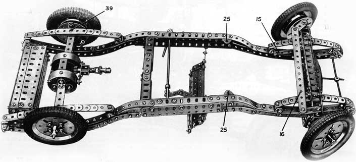
When both side girders have been built they must be connected together as shown in Fig. 2. The main connection consists of a substantial girder built up from two 21/2" and two 3" Angle Girders, together with two 3" Flat Girders. These parts are bolted together to form two short deep section girders, and when complete are connected together by a series of 2 1/2" and 1 1/2" Strips as shown in Figs. 1 and 2. In addition to this, the side girders are further interconnected by the front axle. This part is composed of two 51/2" Angle Girders and four 21/2" large radius Curved Strips. The arrangement is illustrated in Fig. 4.
Pag.2
The petrol tank also adds to the structural strength of the model, although this arrangement of course is not in accordance with actual practice. The tank top is represented by two 51/2" Flat Girders, and this is secured to the front face of the tank by means of 1/2" X 1/2" Angle Brackets, the front face being constructed similarly. The tank bottom consists of four 41/2" Flat Girders. Two 3 1/2" Angle Girders, overlapping three holes, form the connection between the tank bottom and front side. The rear face of this part of the model consists of a 5 1/2" Flat Girder held in place at its upper edges by two 1/2" x 1/2" Angle Brackets.
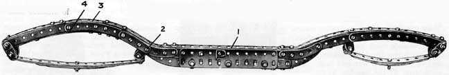
fig.3, One of the main frames removed from the chassis
Each end of the tank consists of that are held in place by means of two 6 1/2" Rods and one 8" Rod. These Rods pass through 1/2" x 1/2" Angle Brackets, Collars being used to hold the Flat Girders in place. The outer extremities of the the main chassis members by Collars.
The Front Wheels and Steering Mechanism
In Figs. 2, 4, and 6 the front portion of the chassis is shown, Fig. 4 giving a striking impression of the low raking lines of the model. Each side of the front axle is fitted with a pair of 2 1/2" large radius Curved Strips as already described, and these carry a pair of Double Brackets 5. These two parts form bearings for a short Rod, the lower end of which is fitted with a Crank 6, which is spaced away from the bearing by two Washers. The upper end of the Rod carries a Coupling 7, four Washers being used at this point for spacing purposes. The outer end of the longitudinal bore of this Coupling is fitted with the stub axle, a 1 1/2" Rod, which supports a Face Plate 8.
Six Washers are now placed on the stub axle, and these hold the road wheel in its correct position. The wheel is prevented from falling off the axle by means of a Collar. A Wheel Flange is attached to the 3" Pulley forming the centre of the road wheel, the boss of this latter part being fitted with two bolts and nuts forming a knock-off nut. These knock-off nuts are a conspicuous feature of nearly all modern sports cars.
One of the front brakes is shown in detail in Fig. 10. A Collar 9 is first
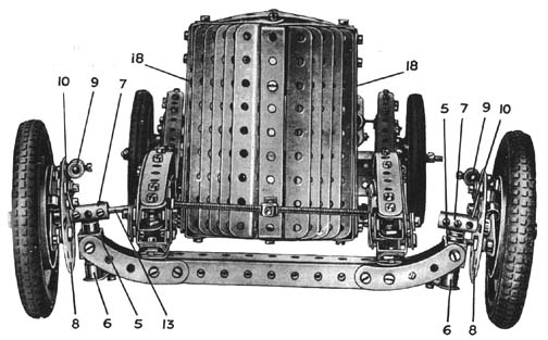
Fig.4 A striking view showing thr rake of the front wheels
secured to the Face Plate, the unoccupied tapped hole of which carries a bolt that forms the locking bolt for the end of the bowden cable. A Flat Bracket 10 is now pivotally attached to the Face Plate by means of a 3/8" Bolt, the end of which forms the support for a Collar 11, this being locked in place by means of its Grub Screw.
The brake shoes are now fitted. Each of these consists of a 1" Triangular Plate held in place by a 1/2" Bolt, and spaced away from the Face Plate by three Washers. The brake shoes proper consist of bolts fitted with two nuts, the nuts forming the actual bearing surfaces for the brake. The Spring Cord 12 holds the brake in the off position. The Coupling 7, shown on the left-hand side of Fig. 4, carries a 1 1/2" Rod 13, the end of which is connected
by means of two Collars 14, Fig. 6, to one end of a 3 1/2" Strip 15. This Strip is slightly bent as shown, and is fitted at its free end with a Flat Bracket by means of which it is secured to a 1 1/2" Bevel Gear. This Gear is fixed on a short Rod that is fitted with a Coupling and is mounted at its inner end in a Double Bracket. It is prevented from moving laterally by means of a Collar. The bore of the Coupling supports the front end of the steering column that carries a 1/2" Bevel meshing with the 1 1/2" Bevel. The method of mounting the steering column is shown in Fig. 1. The two Cranks 6 are now connected together by a 7 1/2" Strip 16. This Strip
forms the track rod and is bent at each end slightly in order to allow for the rake of the front wheels.
The front support for the engine is now fitted. This consists of two 4 1/2" Strips 17 attached at each end by a 1/2" Reversed Angle Bracket. The method of securing the engine to this will be described later.
The Radiator
This section of the model next occupies our attention. The frame consists of two pairs of 4 1/2" Strips 18 fitted at each end with
a l"x1/2" Angle Bracket. At the lower end these Brackets are connected together by means of two 2" Strips, Fig. 5, and at the point where they are joined a 4 1/2"x1/2" Double Angle Strip is fitted. The l"x1/2" Angle Brackets at their upper ends are secured together by two
Pag.3
2" Strips and a 3 1/2" Strip. These Strips are bent slightly in order to arrive at the correct shape in the completed radiator. Two 1/2"x1/2" Angle Brackets are now fitted, and these carry the 31/2" Flat Girder 19. The centre of this Girder is fitted with a Flat Bracket 20 that carries in its upper hole the Threaded Boss 21.
It should be noted here that the Double Angle Strip already mentioned is secured at its upper end to the centre connecting bolt of the two upper 2" Strips.
The imitation radiator shutters are composed of a series of 4 1/2" Angle Girders. They are connected together by means of two 4 1/2" Threaded Rods and are spaced apart by Washers, four Washers being placed between each two. The 41/2"x1/2" Double Angle Strip is fitted with two Double Brackets 22 and 23, the first being secured in place by a nut and bolt. The Bracket 23, however, is secured to the Double Angle Strip by a 2" Threaded Rod shown in Fig. 4. Full use must be taken of the slots in the Angle Girders in order to arrive at the necessary curve characteristic of the Bentley radiator.
The radiator, when complete, is secured to the chassis by means of four 1/2" x 1/2" Angle Brackets 24. These are arranged in pairs, each pair being bolted together to form a corner angle bracket. The 4 1/2" Strips 17 form the point at which the radiator is attached to the chassis. It is further secured by a 2" Threaded Rod, holding the Double Bracket 23 in position. A " spider " taken from a Swivel Bearing is passed on to the Threaded Rod and it supports in its transverse tapped holes the ends of two Threaded Rods. These are attached at their opposite ends to 1/2"x1/2" Angle Brackets and also to the chassis frames, nuts being used to lock them in position. Care must be taken to see that these last-mentioned Threaded Rods hold the " spider " exactly central, as shown in Fig. 4.
The 1" Triangular Plates 25 are now fitted as shown in Fig. 6. These will be used later for carrying the two rear engine supports.
The Rear Axle
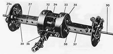
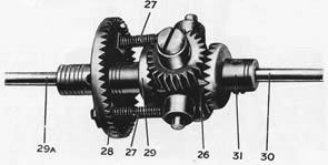
Probably one of the greatest difficulties experienced in the building of a Meccano Chassis is that of constructing a compact and efficient differential and back axle casing. In Figs. 7 and 8 one solution to the problem is illustrated, and it is very doubtful whether a smaller complete back axle casing is possible with the vise of Meccano parts only. The
differential is shown detached from the casing in Fig. 8. A Coupling 26 is fitted in its centre plain hole with a 1 1/2" Rod carrying at each end a Collar. These Collars are held in place by the 1" Threaded Rods 27 by means of which the Coupling is secured to a 1 1/2 Contrate Wheel 28, representing the crown wheel.
Between the Coupling and Contrate 28 a 3/4" Contrate 29 is fitted, three Washers being used for spacing purposes. The 4 1/2" Rod 29A, on which this last-mentioned Contrate is carried, forms one side of the back axle, the opposite side of which consists of a similar Rod 30 carrying the Contrate 31. The planetary pinions are now fitted. Each of these consists of a 3/4" Pinion secured, boss outward, to the Coupling 26 by means of a Pivot Bolt. These Pinions mesh with the 3/4" Contrates already described.
The Rod 29A is now fitted with a Boiler End 32, spaced away from the Contrate 28 by means of six Washers. In a similar manner a second Boiler End 33 is fitted, two Washers being used to space this from the differential. Three 2" Strips, one of which is shown at 34, are now fitted on the inside of the Boiler Ends. A fourth 2" Strip 35 is also fitted but this is attached to the outside edges of the Boiler Ends3/8" Bolts are used for securing this Strip in position, and two Washers are placed between the Strip and the Boiler Ends on each Bolt ; one Washer is also placed under the head of each Bolt. A Double Bent Strip is now bolted to the 2" Strip in the manner shown in Fig. 7, and this, together with one of the holes in the Strip 35, forms a bearing for the Rod 36. The inner end of this Rod is fitted with a 1/2" Pinion that meshes with the crown wheel 28. The Rod at its outer end is fitted with a Universal Coupling.
The construction of the rear axle casing can be followed fairly easily from Fig. 7. Three 2 1/2"x 1/2""Double Angle Strips are first secured to the Boiler End 33, being arranged to form a channel section girder. The outer turned-up ends of these are bolted to a Face Plate, and care must be taken to see that the centre hole of the Boiler End is in accurate alignment with the hole in the boss of the Face Plate.
The 2 1/2" Strip 37 must now be fitted. This part is secured to the 1/2" x 1/2" Angle Bracket 38, which in turn is bolted to the Boiler End 33.
Pag.4
The opposite end of the Strip is fitted with a 1/2" Bolt 39 by means of which a 1" X 1/2" Angle Bracket is held in place. The elongated hole of this Bracket is bolted to one of the outer holes of the Face Plate, this form of construction being necessary in order to allow the leaf spring to be accommodated on the inner face of the Bracket. It should be noted here that the long bolt shown holding the rear spring together in Fig. 3 is only included during the early stage in the building of the model, and may be withdrawn immediately the complete rear axle is ready to be fitted.
The opposite side of the rear axle casing is now built, its construction being carried out in an exactly similar
manner to that already described.
Brakes are next dealt with, and no difficulty should be experienced with these if the instructions given for building the front wheel brakes are carefully followed. In the illustration showing the complete back axle, the bolt heads are shown used as the brake surfaces in place of nuts shown in Fig. 10. This arrangement was adopted in order to allow narrow rubber tubing to be placed over the bolt heads, thereby increasing the efficiency of the brakes. If desired, however, the front wheel arrangement may be used in place of this.
The back axle is now ready for fitting into the chassis, and this is accomplished in the following manner. The temporary bolts used for holding the leaves of the rear springs together are first removed, after which the shanks of the bolts 39 are passed into the vacant holes. By careful manoeuvring, this will be accomplished without difficulty. When the bolts are finally in place the securing nuts are fitted as shown in Fig. 2. The rear wheels are now fitted, these being similar to those used at the front. They are locked on the axle, however, and knock-off nuts are represented by Collars fitted with two bolts.
Gear-Box
This is probably the most difficult section of the model to construct, and strict attention should therefore be given to the following description Care must be taken also in lining up the various shafts and bearings, as upon
this depends the successful working of the model. It is of the four forward speed and single reverse type, and although its various gears are not in constant mesh, as with most modern gear-boxes, it gives an excellent insight into the operation of an actual gear-box.
The frame consists essentially of two 3 1/2" Angle Girders 40 and 41, connected together by four 2 1/2" Strips and four Angle Brackets 42. These four cross members form a rectangle 3 1/2" long and 2 1/2" wide. A 2 1/2" Angle Girder 43 is also fitted, the purpose of which will be described later. A
3 1/2" Strip 44 is bolted to the inner flanges of the Strips 42. This Strip 44 forms the support for two 1 1/2" X 1/2" Double Angle Strips 45 and 46 that form the bearings for the driving and driven shafts respectively.
Each built-up girder 42 carries at each end a 1/2" Strip, and these support a 2 1/2" Strip 47 at one end of the gearbox and a similar Strip 48 at the other end. In addition, the Strips form supports for two 2 1/2" Angle Girders 49 and 50.
The layshaft guides and supports are now fitted. In Fig. 11 the lay-shaft for third and top gears is shown. A 41" Rod 51 slides in holes the Strips 42 as shown. of It carries a Collar 52 and also two
Couplings, the upper holes of these latter parts forming the bearings for the lay-shaft 53. The Collar 52 is fitted with a Flat Bracket, part of which is shown at 54, Fig. 12. The Flat Bracket is held in place by a f" Bolt, under the head of which is placed two Washers. Two Washers are also placed for spacing purposes between the Flat Bracket and Collar 52, the Bolt passing through the slotted hole of the Bracket at its inner end. The Flat Bracket will now be found to bridge the gap between the Girder 41 and the Strip 44, and its ends must be bent inward slightly until they press lightly against these two parts. By this means the Rod 51 is prevented from
turning. It is able to slide horizontally, however, and its movement in this. direction is limited by the bolt head 55 on one side and the securing bolt of the Double Angle Strip 45 on one the other.
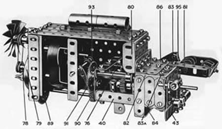
Fig.9. The engine unit with one side removed to show the internal construction
The slide on the other side of the gear-box must be fitted before proceeding further with the construction. This is built up and fitted in an exactly similar manner to that already described, with the exception that the two Couplings carrying the lay-shaft are arranged differently. Their positions are indicated at 56 and 57 in Fig. 11.
The driving shaft 58 is a 2 1/2" Rod and carries a Collar and 3/4" Pinion 59 between the Strip 48 and Double Angle Strip 46. On the opposite side of the Double Angle Strip-is fitted a 1/2" Pinion 60. It should be noted that this Pinion is only occupied for half its length by the Rod 58, the remaining portion of the hole forming a support for the inner end of the Rod 61. This Rod is 31/2" in length, and is fitted with the 1/2" Pinion 62 and 3/4" Pinion 63, which are secured on the Rod between the Double Angle Strip 45 and Pinion 60. Between the Double Angle Strip and 2 1/2" Strip 47 a 1" Gear 64 is locked in place on the Rod, being secured as near to the 2J" Strip as possible without actually touching. The boss of this Gear must fall inward in order to give the Pinion 65 sufficient clearance. A Collar is now secured outside the gearbox on the Rod 61 in order to prevent that Rod from moving laterally.
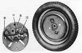
Fig.10. One of the front brakes with its road wheel.
The lay-shaft 53 is next fitted. This is journalled in the upper plain holes of the two Couplings secured to the Rod 51. It consists of a 2 1/2" Rod and it is fitted with a 1/2" Pinion 66 and 3/4" Pinion 67. The boss of the Pinion 66 and the Collar 68 prevent the Rod from moving laterally, independently of the Rod 51. As already mentioned, this lay-shaft operates the third and
top gears, which are arranged as follows. When the Rod 51 is move to its extreme 59, 66, 67 and 62 are in engagement, and this results in top gear. Neutral is obtained by moving the lay - shaft partly to the front. When the Rod is into the forward position the two
Pinions 60 and 62 are locked together by the Pinion 67, thus resulting in a straight-through drive that is used for third gear.
The gear-box is now ready for receiving the second lay-shaft. The disposition of each of the Couplings supporting this has already been described, and the 2 1/2" Rod forming the lay-shaft may be fitted. 83 95 81 Between the two Couplings are fitted a 3/4 Pinion 69 and Collar 70. To the left of the Coupling 57 a 1/2" Pinion indicated at 71 is secured, and this forms one of the second gear and reverse gear Pinions. The bottom gear pinion 65 consists of the pinion taken from an Bl Electric Motor. This will be found to mesh accurately with the 1" Gear 64 when the lay-shaft is adjusted properly. First and second gears are obtained in the following manner. When the Rod 61 is iiL its mid position, the Pinions 60 and 69 are in mesh together with the pinion 65 and 1" Gear 64. Slight movement forward results in the pinion 65 and Gear 64 being thrown out of mesh, and gives neutral gear. Further forward movement brings the Pinions 63 and 71 into mesh, while Pinions 60 and 69 still remain in mesh.
Two corner angle brackets formed from ½”x1/2" Angle Brackets are now fitted, the positions of which are shown in Fig. 11. The inner flanges of these two parts form bearings for a 3" Rod carrying a 1/2" Pinion 72 and Collar 73. The two parts are spaced slightly apart in order to accommodate the end of a Pawl 74 that is secured on a Rod 75 journalled in the holes of the two ends of the gear-box as shown. A Collar limits the backward movement of the Rod 75. The Pinion 72 is normally held by the gate in the position shown, as will be described later, and is only thrown into gear when the first and second gear lay-shaft is in neutral. It is then moved to the rear and engages with Pinions 63 and 71.
Pag.6
Thus the drive for reverse gear is taken through Pinions 60, 69, 71, 72 and 63, and the resulting gear ratio is midway between second and third gears of the forward speeds. Figs. 9 and 12 should be constantly referred to, as they will make the construction of the gear-box considerably simpler. A 3J" Strip 76 is next fitted as shown in Fig. 9, forming a bracing member for the Double Angle Strips 45 and 46.
The Engine Casing
A 5 1/2"x3 1/2 " Flat Plate 77, Fig. 12, is fitted at the front end with a 3 1/2" Angle Girder. This is connected to a 2 1/2" Girder by four 2 1/2" Strips and one 2" Strip, a space being left above the second 2 1/2" Strip from the bottom in order to accommodate the Rod carrying the fan pulley 78. A Flat Bracket is bolted to each 3 1/2" Angle Girder in order to partially close the gap, and also to form supporting points for the shanks of two 1/2" Bolts. The Bolts secure the Wheel Flange and Bush Wheel 79 in place. The bottom hole of the Bush Wheel carries a Threaded Pin by means of which the front engine mounting, an End Bearing, is held in place. The top hole of the 3 1/2" Girder is fit ted with a 2" Girder, and this is held in place by means of a vertical 1 1/2" Strip.
The rear of the 5 1/2"x3 1/2" Flat Plate 77 is fitted with a 1 1/2" Angle Girder attached to a similar Girder 80 by means of two 2 1/2" Angle Girders. The space enclosed by these four short Girders is filled in with two 1 1/2" Strips. The horizontal flange of the lower 2 1/2" Angle Girder is fitted at one side with a 3" Angle Girder 81 and at the other with a 1 1/2" Angle Girder 82. It should be noted that many of the 1 1/2" Strips used in the construction of this part of the model are only used for "purposes and may be dispensed with if necessary. filling in"
The gear-box is now fitted, by adding the nut and bolt 83, Fig. 9. The nut and bolt 83A is that which supports one of the built-up corner angle brackets mentioned earlier. The bottom Girders of the gear-box are now connected by two 1 1/2" Strips and one 2" Strip to the Girders 81 and 82 respectively, and the bottom holes of the 2" Strips support a 2 1/2/"x 1/2" Double Angle Strip 84. The same bolts that secure this last-mentioned part also hold in place the two 1 1/2" Strips 85, Figs. 12 and 13. Washers are placed for spacing purposes between the ends of the Double Angle Strip 84 and the 2" Strips. The 2 1/2" Strip 86 is
Reference to Fig. 1 shows the form that the right-hand side of the engine takes. This consists of a 5 1/2" X 2 1/2" Flat Plate secured at the front end to the 2 1/2" Angle Girder already mentioned, and at the rear to the Strip and Girders forming the side of the gear-box.
A 5 1/2" Flat Girder 83 is fitted at its lower edge with an Angle Girder of similar length. This Angle Girder supports the bottom ends of two 2" Threaded Rods each of which carries a Worm and the shank of a Spring Buffer held in place by a Nut. Collars are used in order to raise the Worms slightly. These two fittings represent the S.U. Carburetter fitted to the original machine. They are both connected together by a balancing pipe represented by three 3 1/2"x1/2" Double Angle Strips.
This section of the engine carrying the carburetters is held in position by a bolt that enters the transverse tapped hole of a Threaded Boss secured
on the inside of the top of the engine. This arrangement enables the 5 1/2" Flat Girder to be fitted when the remainder of the engine has been built. The bolt by means of which the Threaded Boss is attached to the top of the engine also secures in place a Sleeve Piece, and this, together with a second similar part, represents the air-intake.
Fitting the Power Unit
When the construction has reached this stage the Electric can be incorporated, which is done by temporarily removing the Flat Plate 77. The method of carrying the Motor is shown in Fig. 9, and it should be noted that it cannot be secured until Plate 77 is replaced. The front end of the armature shaft carries a 1" Gear that meshes with a 50-teeth Gear locked on the Rod carrying the Pulley 78, as shown in Fig 12. This Rod is also fitted with a 1/2" Pinion that engages with a 57-teeth Gear 89. The 5" Rod carrying this Gear also carries a 1/2" Pinion 90 meshing with a second 57-teeth Gear 91 that is free to rotate on the Rod 58 of the gear-box. Between this Gear and the end of the gear-box a collar and portion of a Compression Strip is fitted as shown in Fig. 12. A 1/2" loose Pulley fitted with a 1/2" Rubber Ring is now-passed on to the Rod and is held firmly against the face of the Gear 91 by a 7/8" Bevel 92. This Bevel is locked on the Rod and forms the fixed member of the clutch.
The clutch withdrawal mechanism is shown in Fig. 9. It is operated by a Crank 93 fitted with a 1 1/2" Strip 94, and this is connected by a Double Bracket and Strip, as shown in Fig. 12, to the clutch pedal 95. The Plate 77 is now replaced and the dynamo 97 and exhaust system fitted. When these
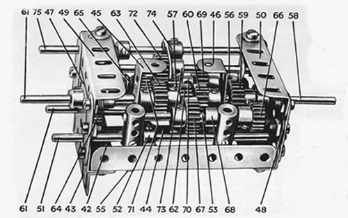
Fig.11. The complete four-speed forward and reverse gear-box.
Pag.7
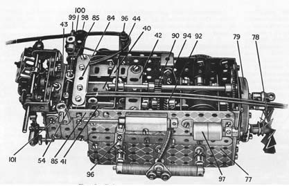
Fig.12 Underneath view of complete engine unit
are in place the rear engine supports 96 are fixed in position, the threaded shanks of the Threaded Pins being used to secure the engine to the 1" Triangular Plates 25 mentioned earlier. The method of fitting the front engine support has already been described. To complete the transmission the cardan shaft and Universal Couplings are fitted, as shown in Fig. 1.
The construction and operation of the " gate " and gear selectors are shown in Figs. 9, 12 and 13, and therefore need no further description.
The Brake Mechanism
The foot brake pedal 98, when depressed, presses against a 1" Rod 99, and this action operates a Collar carrying the 1/2" Bolt 100. This Bolt holds a second Collar firmly in position, and carries in its two opposite tapped holes two 3/4 " Bolts round which pass the wires, which are connected at their opposite ends to the Flat Brackets of the brakes. These wires form the inner cores of bowden cables, the outer sheathing of which is represented by Spring Cord. The sheathing is secured in place at the brake drum ends in the Collars 9 as already described. The other ends of the lengths of Spring Cord are clamped between the 2 1/2" Strip 84 and a 2 1/2" x 1/2 " Double Angle Strip as shown in Fig. 12.
The hand brake lever, which is secured to a transverse Rod journalled at its free end in a 1 1/2" Angle Girder, is limited
in its movement by a 1/2x1/2
" Angle Bracket and 3/8" Bolt as shown in Fig. 1. The link mechanism, by means of which it is connected to the 1" Rod 101, Fig. 12, is shown in Fig. 2.
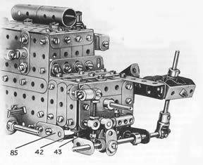 Fig.13. Rear en of engine unit showing gate and selector rods.
| 5 of Nº | 1b | 2of Nº | 14 | 2of Nº | 31 | 2of Nº | 80a | 4 of Nº | 142b |
| 23 " " | 2 | 2" " | 15 | 2" " | 32 | 2" " | 80b | 3" " | 147 |
| 20" " | 2a | 5" " | 15a | 452" " | 37 | 1" " | 31 | 3" " | 147b |
| 10" " | 3 | 4" " | 16 | 98" " | 37a | 6" " | 82 | 1" " | 155 |
| 3" " | 4 | 3" " | 16a | 200" " | 38 | 6" " | 89 | 2" " | 162a |
| 30" " | 5 | 5" " | 16b | 1" " | 40 | 12" " | 90 | 3" " | 163 |
| 22" " | 6 | 3" " | 17 | 2" " | 43 | 7" " | 103 | 2" " | 164 |
| 14" " | 6a | 9" " | 18a | 2" " | 45 | 4" " | 103c | 1" " | 165 |
| 2" " | 8b | 3" " | 18b | 4" " | 48 | 3" " | 103d | 1" " | 166 |
| 8" " | 9 | 4" " | 19b | 8" " | 48a | 2" " | 103e | ||
| 10" " | 9a | 1" " | 20a | 3" " | 48b | 4" " | 103h | ||
| 3" " | 9b | 1" " | 23 | 1" " | 48c | 4" " | 109 | ||
| 3" " | 9c | 4" " | 23a | 1" " | 52 | 11" " | 111 | ||
| 7" " | 9d | 1" " | 24 | 2" " | 55a | 24" " | 111a | ||
| 2" " | 9e | 5" " | 25 | 5ft." " | 58 | 12" " | 111c | ||
| 3" " | 9f | 8" " | 26 | 50" " | 59 | 6" " | 115 | ||
| 30" " | 10 | 1" " | 27 | 6" " | 62 | 1" " | 116a | ||
| 12" " | 11 | 2" " | 27a | 3" " | 62b | 2" " | 120a | ||
| 74" " | 12 | 1" " | 28 | 13" " | 63 | 1" " | 120b | ||
| 2" " | 12a | 2" " | 29 | 2" " | 63b | 2" " | 125 | ||
| 8" " | 12b | 1" " | 30 | 4" " | 64 | 1" " | 136 | ||
| 4" " | 12c | 1" " | 30a | 1" " | 70 | 5" " | 137 | ||
| 3" " | 13a | 1" " | 30c | 10" " | 77 | 2" " | 140 |
1.El electric Motor.
1of Nº 25
2 of Nº 89b
(not include in Outfiit)
5ft. of 26
S:W:G. bare copper wire
Pag.8