(No. 3) |
New Meccano
Motor-Cycle and Sidecar
THE first attempt to construct a cycle to be driven by a petrol engine was made in 1885 by Daimler, the famous engineer who was responsible for so much pioneer work with motor-cars. No really serious effort to produce a practical machine was made until ten years later, however, when a motor bicycle was invented by Colonel Holden, and patented in 1896 and 1897. The original machine is at present in the Science Museum at South Kensington. It has four horizontal air-cooled cylinders, placed two in line on each side of the frame. The carburetter is of the old surface type, the petrol vapour being mixed with a stream of air that passes over a diaphragm of copper gauze that is always wet with petrol. Ignition is by coil and accumulator.
The next noteworthy effort was made by Messrs. Werner in the early years of the present century, and the principal features of their model have been retained to this day. They used a single vertical cylinder set low down in the frame, and the crank case formed an integral part of the frame of the machine. A small pulley on the crankshaft drove a larger one, fixed to the back wheel by means of a belt; and pedals were retained in order that the rider could assist the engine when necessary.
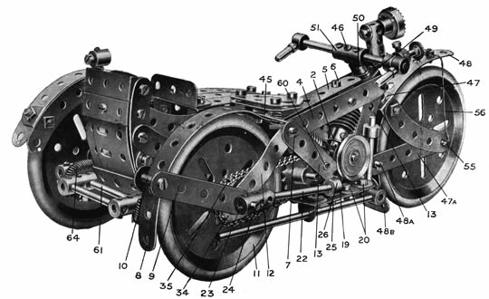
Fig.1.General view of Motor Cycle Combination
The carburetter represented a great advance on that used on Holden's machine, the incoming air being charged with petrol vapour by a spray controlled by a float feed, as in modern instruments. Ignition was still by coil and accumulator. The tank was fitted
Pag.1
to the frame above the engine, and was divided into compartments for petrol and oil as on modern machines, except that there was an additional compartment in which the accumulator was carried. The drive to the rear wheel was by belt.
Great improvements have, of course, been made since that time, both in the efficiency of the engines and in the methods of transmission of power to the rear wheel. The use of a magneto for ignition became universal in comparatively early days, but even as late as 1914 belt drive was still fairly common. The machine that won the Senior T.T. Races in that year had a single cylinder set vertically in the frame in the usual fashion, and a magneto was used for ignition. It was chiefly notable for such special features as a variable speed gear that made use of variable belt pulleys on the engine shaft and the rear wheel, and a multiple - plate clutch operated from the handle-bars.
In modern machines the belt has been completely replaced by chains and sprocket wheels, while gear boxes with toothed gear wheels givingvarious ratios have become universal. In most cases these differ from the average motorcar gear box in that all the gear wheels are always in mesh, and changes are made by means of movable dog clutches.
The model described in this leaflet is an excellent example of Meceauo miniature ei igin eering, and offers a remarkable testimonial to the adaptability uf the system. Its
construction will prove no light tax on the ingenuity ol'even long-experienced Meccano boys, and it is undoubtedly a task calling for nimble fingers.

Fig.2. The Motor Cicle, showing near side.
Building the Meccano Motor Cycle
The only item included in the model that is not a regular Meccano part consists of a small elastic baud ; this should be about 1 3/4" in length when fully extended. The novel use of the Curved Strips in the construction of the sidecar, by which a pleasing1 streamline effect has been obtained, forms an interesting feature of the model. Both the sidecar and saddle are mounted on springs.
Each engine cylinder consists of a Worm Wheel, secured by its set-screw to the shank of a Bolt passed through a Flat Bracket 2 carried from a Double Bracket 3 (Fig. 2). The tank consists of two 3 1/2" Strips 4 (Fig. 1) and one 3" Strip 5, held together by Double Brackets at 6 and 7. A 5 1/2" Strip 8 is bolted by its end hole to the end of the Strip 5, and is bent round as shown to form the rear mudguard. It is clamped in position between two 2 1/2" Strips 9 by means of a 3/4" Bolt 10. The driving wheel 11 is carried in the ends of 2 1\2" Strips 12, which are bent slightly as shown in Fig. 4} as also are the Strips 9.
The V-shaped engine frame is built up from 2 1/2" Strips 13 converging upon 1" Triangular Plates 14 (Figs. 4 and 2). The side 2 1/2" Strips have been removed in Fig. 2 in order to reveal some of the engine details; normally they are
secured by the Bolts 15, 16, 17, and 18. A 2" Flat Girder 19 (Fig. 1) is secured to two Angle Brackets 20 bolted to the base of the outer 1" Triangular Plate. A similar Flat Girder 21 (Fig. 2) is attached to the first Girder 19 by means of Bolts passed through the elongated holes of both Girders.
A tie-rod provided on the right - hand side of the machine consists of a 2 1/2" Rod 22 (Fig. 1) nipped in the end of the Coupling 23, in which the back axle 24 is allowed to rotate freely. A set-screw 25, carrying one Washer, is passed through a hole in the Flat Girder 19, and entering the threaded bore of a Collar 26, grips the Rod
22 fast in position. Another tie-rod of different construction is fitted to the left-hand side of the machine. This comprises a 4 1/2" Axle Rod 27 (Fig. 2) secured to the Flat Girder 21 by means of a Collar and set-screw 28, in a similar manner to that just described. Two Couplings 29 and 30 are mounted on the Rod 27. Coupling 30 forms an additional support for the back axle, and the centre transverse hole of the Coupling 29 is employed as a bearing for a 2" Axle Rod 31 (Fig. 4). This Hod 31 carries a 1/2" fast Pulley 32 (Fig. 2), and a 3/4" Sprocket Wheel 33 (Fig. 4).
The back axle 24 (a 2" Rod journalled through the Couplings 23 and 30
Pag.2.
and Strips 9 and 12) is gripped by the set-screw of the driving wheel 11, and carries a 1" Sprocket Wheel 34 (Fig. 1) which is caused to engage with the 3/4" Sprocket 33 by means of a Sprocket Chain 35, composed of 39 links. The 1/2" Pulley 32 (Fig. 2) is connected to the shaft of the flywheel 36 by means of a small rubber band 37, which passes round the groove of the Pulley and round the flywheel shaft itself, being guided between a Washer and Collar with set-screw 38. Hence, as the machine runs along, the flywheel is caused to revolve at considerable speed.
A 5" Rod 39 and 2" Rod 40 (Fig. 4) represent the exhaust pipe. The Rod 39 passes through the Angle Bracket 41, and is secured in the end of the Coupling 42, representing the silencer; the 2" Rod 40 is secured in the centre transverse hole of the Coupling 42, while its upper end, passing through the Collar 43, is gripped by its set-screw. The latter, carrying a Washer, passes through the centre hole of the Strip 13 before entering the Collar. The short exhaust pipe 40 is duplicated on the other side of the machine (see Fig. 2) ; it should be noted that the Coupling 44 in this illustration is connected to Coupling 42 (Fig. 4) by means of a 1" Axle Rod.
The saddle is composed of two Flat Trunnions secured to the framework by means of three 1/2" Bolts. A l 1/2" Strip 45 (Fig. 1), bolted transversely to the second hole of the 5 1/2" Strip 8, forms supports for the rear saddle springs. The saddle is mounted on three Compression Springs, placed one on each of the bolts that hold the Flat Trunnions in position.
The steering column, handle-
bars, etc., are constructed as follows :—a 2"Rod46 is passed through the Fork Piece 47 and its end enters the centre hole of the 5 1/2" Strip 48,
which is bent round to form the front mudguard. A Washer is then placed against the boss of the Fork Piece and the Rod 46 is journalled through two Double Brackets 49, which are placed one within the other and bolted to the ends of the Strips 4 and 13. Three Washers, a Collar 50, and Coupling 51 are then placed in position on the steering column as shown. The handlebars are built up from Threaded Pins, Collars, and two 1 1/2" Rods, carried from the Coupling 51.
The head-lamp is composed of a 3/4" Contrate Wheel 52 (Fig. 4) secured to the shank of a 3/4" Bolt passed completely through the Coupling 53. The latter is secured to a Bolt passed through an Angle Bracket, which in turn is secured
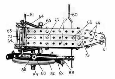
Fig.3.Underneath view of the Sidecar.
by a set-screw 54 to the Collar 50.
The front wheel forks consist of 2 1/2" Strips 47a (Fig. 1) and 2 1/2|" Curved Strips, all of which are slightly splayed to allow free movement of the road wheel. The mudguard 48 is clamped between the Strips 47a by means of a 3/4" Bolt 48a passed through their end holes, in a similar manner to the Bolt 10 on the rear mudguard 8. The set-screw of the front road wheel is removed in order that it may revolve independently of the 1 1/2" Axle Rod 55. The wheel is held in a central position on its axle by means of a Collar and three Washers mounted within the forks on one side of the wheel, to equalise the width of the boss on the other. The mudguard 48 is secured by means of a tie 56. This consists of a Meccano Heald (Part No. 101), the end holes of which are slipped over the axle 55 before the 2 1/2" Curved
Strips are placed in position. The Heald is then doubled beneath the Curved Strip and taken over the Strip 48, and thence down to the opposite end of the axle 55. It is secured to the mudguard by means of a Bolt passed through its centre hole. A 1" Triangular Plate 48b bolted to the second hole of the Strip 48 forms a "splash-guard."
A "Klaxon" horn 57 (Fig. 4) is provided. It is constructed from the "ram" of a Meccano Spring Buffer, the screwed end of which engages the threaded bore of a Collar 58 mounted on the handlebars. A Collar 59 with set-screw added represents the operating handle and completes the realistic effect.
The undercarriage of the sidecar is built up from a Crank Handle 60 (Fig. 3) and 3 1/2" Rod 61 connected by Couplings and 3 1/2" Rod 62. Two Couplings and a 2" Rod 63 serve as a luggage carrier, while Bolts inserted in the Couplings carry Springs 64, between which the car is suspended. The springs are attached to the car by means of a 2 1/2" Rod 65. A set-screw 66 passed through the bottom of the car enters the threaded bore of a Collar on the Crank Handle 60, so holding the car in position.
Constructional details of the Sidecar
Each side of the car is composed of the following; parts (see Fig. 4):
67, 2 1/2" and 5 1/2" Curved Strips overlapped two holes and bolted together;
Pag.3
members, with the exception of 68, are bolted to a Corner Bracket 71 in the nose of the car. The floor (Fig. 3) is composed of two 44" Strips 72, a 5 1/2" Strip 73, and two 2 1/2" Strips 74, bolted to 1 1/2 x 1/2 Double Angle Strips 75. The top (Fig. 4) consists of three 3" Strips 76, two 2 1/2" Strips 77, and one l 1/2" Strip 78, also secured to l 1/2x 1/2" Double Angle Strips. The back is built up from three 1 1/2" Double Angle Strips, bolted between the corner 2 1/2" Curved Strips 80, and two 2 1/2" Flat Girders slightly bent as shown, and secured by a Bolt 79. All four sides taper towards the nose of the car and are secured to two Double Brackets bolted together by the Nut and Bolt 81 (Fig. 3).
A seat is provided within the sidecar. This is constructed from two 1 1/2" Flat Girders secured, by means of a Bolt passed throughthe elongated hole in the end of each, to a 1/2" Reversed Angle Bracket. The latter is bolted to the floor of the car by means of the screw 75 (Fig. 3).
The third road wheel 82 runs freely upon a 1 1/2" Rod bolted in the top transverse bore of a Coupling 83. Two Washers are placed on the 1 1/2" Rod between this Coupling and the wheel, while the latter is held in place by the Collar 84. The Coupling 83 is secured to the Rod 62, which passes through its centre. A 2 1/2" Strip 85 (Fig. 4) is secured to the 1/2" Bolt 86 (Fig. 3) passed through the lower end of Coupling 83.
The Strip 85 serves to support the mudguard, which is constructed from 5 1/2" and 2" Strips
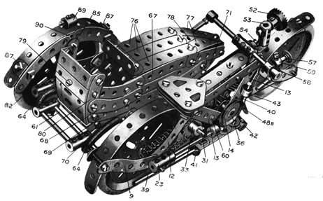
Fig.4. View from above.
overlapped two holes and bolted together. The mudguard is bent round the wheel as shown in Fig. 4 and carries two 2 1/2" Curved Strips secured by Angle Brackets 87. A Flat Bracket 88 (Fig. 3) is bolted to the end hole of the 2" Strip and engages the Rod 62.
The side-lamp 89 consists of a Threaded Boss, screwed to the upturned shank of a Bolt which serves to secure th^ Angle Bracket 90.
The sidecar may be quickly connected or detached from the motorcycle. The Crank Handle 60 passes through the Strips 13 of the engine-frame (its extreme end is just visible in Figs. 1 and 4),while the Rod 61 enters the end hole of a Coupling 91 (Fig. 2) where it is gripped by the set-screw. It will be seen, therefore, that by loosening this screw the sidecar may be immediately detached, and the motorcycle used as a solo machine if so desired.
All three wheels are fitted with Meccano Rubber Rings (Part No. 142) to represent pneumatic tyres.
Amongst other features that may be added if desired are a pillion (constructed from two short Flat Girders "sprung" by a method similar to that employed in the saddle) and a rear stand, for attachment if the model is used as a solo outfit. Still further refinements, such as number-plates, etc., would give the finishing touch to the compact and realistic appearance of the model.
List of Parts Required to Build the Motor-Cycle and Sidecar
MOTOR-CYCLE.
2 of No. 2 |
1 of No. 15 |
1 of No. 23A |
2 of No. 90 |
2 of No. 11.) |
||||
2 |
3 |
1 |
ISA |
2 |
32 |
6*" |
94 |
1 „ 110 |
1 |
4 |
1 |
1G |
28 |
37 |
1 |
96 |
1 „ 120A |
10 |
5 |
5 |
17 |
10 |
37A |
1 |
96A |
3 „ 120B |
1 |
6A |
4 |
ISA |
16 |
38 |
1 |
101 |
2 „ 126A |
2 |
10 |
1 |
18B |
n |
59 |
2 |
103G |
2 „ 142 |
6 |
11 |
2 |
19B |
8 |
G3 |
3 |
111 |
Small elastic |
4 |
12 |
1 |
22 |
3 |
77 |
3 |
111A |
band |
SIDECAR.
| 2 of Nº | 2 | 3of Nº | 12 | 1of Nº | 37a | 8of Nº | 90 |
| 2 " " | 2a | 2 " " | 16 | 3 " " | 38 | 2 " " | 103f |
| 5 " " | 3 | 1 " " | 16a | 2 " " | 43 | 2 " " | 103h |
| 5 " " | 5 | 1 " " | 17 | 7 " " | 48a | 1 " " | 111a |
| 2 " " | 6a | 1 " " | 18a | 4 " " | 59 | 1 " " | 125 |
| 1 " " | 9f | 1 " " | 19 | 5 " " | 63 | 2 " " | 133 |
| 1 " " | 10 | 1 " " | 19b | 1 " " | 64 | 1 " " | 142 |
| 2 " " | 11 | 55 " " | 37 | 6 " " | 89 |