(Mo. 7) |
SPECIAL INSTRUCTIOH LEAFLETS FOR BUILDING MECCANO SUPER MODELS
Meccano Platform Scales
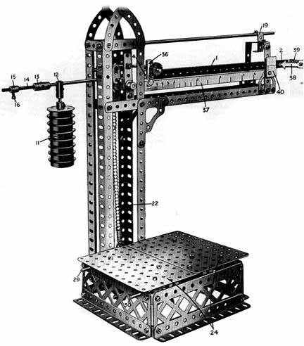
Fig.1 General view of the Meccano Plat-form Scale
A Model that will
Accurately Register
Any Weight from 1/2 oz. to 4 1/2 lb.
The ilustrations to this leaflets show the model built in Red-Green |
The necessity for some means for weighing must have beenfelr by man from the time he emergedfrom a condition of primitive savagery. How the erliest weighing operations were carried do not know, but it appears certain that the oldest form of
ir that this form of balance was used by the ancient Egyptians, doubt the balance referred to frequently in the Bible was of type. In all probability the same means of weighing was ancient China long before the Christian era, for civilisation
ly beginning to dawn on the nations of Europe.Modern weighing machines present such a variety of forms
that it is difficult to recognise in some of them any of the characteristics of the the simple oil-fashioned scales. In cases where a high degree of exactitude is unnecesary,and where a small compact machine is
required, it is customary to make use of a spring balance, which
relies for itis actionupon the fac that the extend to wich a coil spring is drawn out varies ill accordance with the weight imposed upon it, and is constant for each definite weight.
This principle
n the complete Manual of Instructions, and is used with complete measuring tensional forces in various kinds of scientific apparatus, but all spring balances have the disadvantage that the springs gradually lose some of their elasticity and become slightly
. The majority of balances and weighing machines. therefore, are constructed without using springs of any kind, The more complicated types incorporate a system of levers. but in
Pag.1
almost every case the essential mechanism consists of some variation of the original balanced arm.
Importance of the " Knife-edge "
the ordinary balance consists of a lever of the firstt order called.the bean , supported at its cente on fulcrum. aat each en ofthe beam ios hung escale pans being for the weights and the other for the object that is to be weighed.
It is necessary that the beam should be able to swing quite freely on its support, and in order to ensure this, the fulcrumconsist of a steel or agate prism or "knife - edge" with its sharp edge at right angles to the direction of the beamand resting upon
a plane of polished steel or agate. This construction reduces friction to the minimum
A pointer fixed to the centre of the beam indicates—by coining to rest in the line of direction from the fulcrum to the
centre of gravity of the beam or by swinging evenly on each side of that line- when balance horizontal, wich occur when the weights inone scale pan exactly balance the object in the other.
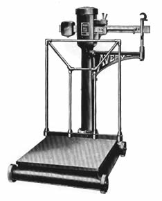 Fig. 2 Portable Plataform Weiher.
The Roman Balance
Very important modification of the equal-armed balance is tlie steelyard or Roman
balance.this consist essentially of a bar of steel suspended near one of its ends
from which hangs the object to be weighed. A weight used as a counterpoise along the longer arm of the bar. The result of placing the counterpoise on the longer arm is to eneble a small weight to balance a very heavy object, thus counterpoise when the arm is level indicates the weight of the object balanced on the shorter arm.
A simple model of a Roman Balance, with which the principle of the model about to be described may be demonstrated, is shown hi Pig. 3, Before using this little model, a counterpoise should, be added to the short arm of the lever so that the longer arm is maintained in a horizontal position when the sliding weight is pushed as closely as possible to the fulcrum. The counterpoise may consist of a series of Strips, etc., and vertically and the sliding weight must be moved outward to restore it to its original position. The distance through which the sliding weight is moved indicates the weight of the object
Roman Balance In its Modern Form
From the simple steelyard has developed the modern commercial platform weighing machines, which is a familiar object in the warehauses and factories of our industrial towns.
In this types of balance the object to be weighed is not hung directly from the steelyard but rests upon a low platform. This arrangement enables heavy and bulky objects, such as sacks full of various materials, to be weighed quickly and with the greatest ease. The whole machine usually is mounted on wheels and thus can be moved easily about a warehouse and operated in any position required.
A typical high-class platform weighing machine is shown in Fig. 2, Such machines are made in various sizes having capacities of from 3 cwt. to 20 cwt. For weighing certain kinds of material the back rail of the platform shown hi the photograph is apt to be inconvenient, and therefore machines may be obtained without this rail
The same type machine is used in railway stations, and in other places, without the
wheels. In many cases the weighing platform is sunk until level with the station platform, so that heavy loads may be moved on to It with the greatest ease. It is generally found arranged in this way in the parcel offices, and larger machines of a similar type are employed in the goods yards and in the yards of mills and factories.
Although differing in outward details from the design of the weigher shown in Fig. 2, the Meccano model nevertheless closely resembles in principle that machine. The Avery weigher is fitted with wheels ao that it may be moved about aa required, and, if desired, the Meccano model may be made portable by mounting the base on 1 " Pulley Wheels or Flanged Wheels,etc. The model was perfected only after much experimental work, and it may well be regarded as still another triumph for the Meccano system
Its internal details, although ,necessarrialy of a complicated nature, have been designed with a view to reducing friction to minimum, with the resut that the model will weigh objects ranging from 1/2 oz. to 4 1/2 lbs.. with remarkable accuracy provided that it is carefully calibrated.
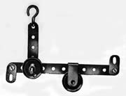 Fig.3 Meccano Model of a Simple Roman Balance
The Steelyard
The framework of the model requires no detailed explanation, for it is shown clearly in Figs. 1 and 5, The steelyard 1, Fig. 1, consists of a 12 1/2 " Strip, and an 11 1/2" Rod extending along the back of this Strip is attached to it by means of Couplings. The Coupling at the outer end is in horizontal position, and is secured to the steelyard bby mean of an
ordinary bolt entering one of its transverse threaded bores, the 11 1/2" Rod being made fast in the longitudinal bore. The 12 1/2 " Strip is similary attached to de Coupling 5,
Fig. 6, the same bolt serving to attach the Strip and to secure the end of the 11 1/2 " Rod in the lowest transverse hole of the Coupling. The Coupling 5 is carried on the end of a 3" Rod 6 which passes through further Couplings 7 and 8 and enters another Cupling in which a 3 1/2 Axle Rod To is mounted. This Rod carries the balance weights 11, which may be secured at any point along its length by means of the Coupling 12. The Rod 10 is extended at its outer
Pag.2
end by a Coupling 13 and a 2" Threaded Rod 14 on which is screwe a Theraded Boss 15
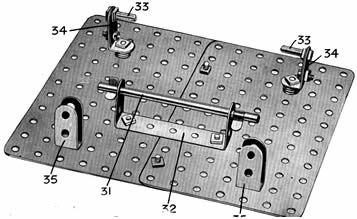 Fig.4 Undernealth View of Plataform
The Knife-edge Bearing
Almost all accurate balances incorporate some form of knife-edge bearing ; in the smaller instruments, as we have already remarked, this usually consists of a triangular prism of agate, an exceedingly hard semi-precious stone, but in the case of large
machines this is obviously impracticable owing to the brittle nature of agate and the amount of this material that it would be necessary to use, and steel therefore often takes the place of agate. In the Meccano model a very efficient knife-edge bearing is
obtained without any deviation from the standard system of parts.
The coupling 7, Fig.6, carries two Centre Forks 17, the points of which rest between the teeth of two 1/2 " Pinion Wheels. Thus the wole weight of the balance arm, including the load imposed upon it, rests on the six hard steel points of the Centre forks with the result that an unusually delicate balance is obtainable. The two 1/2 " Pinions are secured to a 2 " Rod rigidly held in two Cranks, which are attached to a pair of 3 1/2 " Strips pivoted to the ends of a Coupling. The central transverse hole of this Coupling carries an 11 1/2" Rod 18, which passes through the middle hole of this Coupling carries anstrip thatt forms parts of the 18, which passes through the middle hole of a horizontal 1 1/2" Strip that forms part of the framework. Collars are secured to the Rod 18 on both sides of this 1 1/2" Strip, but are spaced sufficiently far apart to allow the Rod a certain amount of freedom to pivot. A stop 19 for the Rod 18 is provided at the outer end of the framework, Fig 1, and consists of a Reversed Angle Bracket to which a nut and bolt are attached.
Two Flat Brachets 20 suspended from the ends of the Coupling & carry in their lower holes a 1" Rod, which is retained in position by Clips. A Hook suspended from this 1" Rod is connected with the leveres 23 in the base of the model by the Sprocket Chain 22 and another Hook, which passes under a 1" Rod held in the end holes of the levers 23, Fig. 5.
Platform Mechanism
The levers 23, Fig. are pivoted on Hooks 24, which are held in position on the 6 1/2" Rod 30 By means of Collars. A central 3" Rod 25 journalled in the Strips 23 is also retained in place by Collars, and carries a special suspension link 26 consisting of a Double Bracket and a 3 /4" Bolt. This link supports a 5" Rod 27, to the ends of which two further levers 28, consisting of 2" Strips, are attached by means of Collars and Spring Clips. The opposite ends of the levers being pivoted to Hooks 28a on the 6 1/2 Rod 29.
The platform, which is shown inverted in Fig 4, is composed of two 5 1/2" x 3 1/2" Flat Plates overlapped one hole and bolted together. A 2 1/2 x 1" Double Angle Strip 32 attached to the underside carries a 3 1/2 Axle Rod 31, whicch is retained in position by Clips. When the platform is in position this Rod rests on the levers 23, Fig. 5, while two Thereaded Pins 33, secured to the 1" x 1 1/2 Angle Brackets 34, secured to the on the levers 23, Fig 5, while two Threaded Pins 33, secured to the 1" x 1/2" Angle Brachets 34, on the levers 28.
Four Washers are placed between each of the Angle Brackets 34 and the underside of the platform, and two Washers are placed on each of the bolts that secure the Double Angle Stip 32. Single Bent Strips 35 bolted to the 5 1/2" x 3 1/2 " Flat Plates fit over the Rod 30 in the base, Fig 5, and form vertical guildes for the platform.
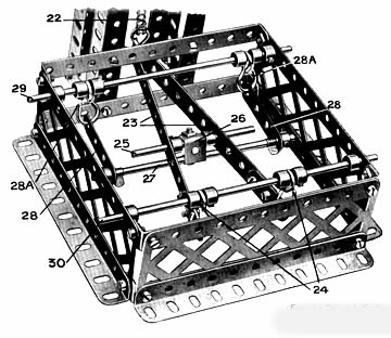 Fig.5 base of Scales
withPlataform Removed.
Pag. 3
The arrangement of the levers underneath theplataform is specially designed to make the machine respond to the slightest pressure, and to ensure that the same weiht placed on any part of the plataform (except at the extreme edges) will produce an equal pull on the Chain 22, whether the load is transmitted to the Chain by way of the Rod 31 and the levers 23 or by the Threaded Pins 33 and the levers 28.
Details of Indicator, etc.
A weight 36. Fig. 1, consisting of a Strip Coupling, a short Rod, and a 3/4 " Pinion, slides along the steelyard 1 and carries a small pointer cut from cardboard, which indicates the load being weighed by
means of the graduated scale 37. A piece of cardboard 38 should be cut in the form of an arrow and bolted to a Reverse Angle Bracket5 39 in such a position
that it comes to rest opposite a line on the cardboard
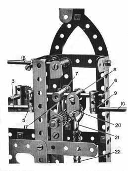 Fig.6
Fig.6
Sectional View of Plataform Scales, Upper Portion, Showing Knife-edge Bearing
indicator 40 when the steelyard is exactly horizontal. An upper stop should be provided for
The steelyard, consisting of a Reversed Angle Bracket and a 1" X1/2" Angle Bracket respectively. The upper stop is clearly seen in Fig. 1 immediately below the stop 19.
In building the model, care should be taken that each part is in the exactposition shown.
When the scales are complete, the steelyard should be balanced carefully by moving the weight 11 and minute adjustment made by means of the Threaded Boss 15 until the arrow 3S is exactly on the line on the indicator 40 when the steelyard is exactly horizontal.
An upper and lower stop should be provide for the sttel yard consisting of reverse angle brackety and 1"x 1/2" Angle Bracket respectively.
The upper stop is clearly seen in Fig.1 inmediately below the stop 19.
In building the model, care should be taken that each part is in the exact position shown.
When the scales are complete, the steelyard should be balance carefully by moving the weight 11 and minute adjustament made by means of the Threaded Boss 15 until the arrow 38 exactly on the line on the indicator 40 when the sliding weiht is in its innermost position.
The bolt 16 should then be tightened up to secure the Threaded Boss on the Threaded Rod 14.
The scale 37 is cut from cardboard, and is provided with extensions at each end by means of which it may be bolted to the 12 1/2 " Strip 1 of the steelyard. To graduate the scale, known weights are placed on the platform, and the sliding weight 36 is moved along the steelyard until the arrow 38 points once more to the line on the indicator 40. The exact position of tile pointer attached to the weight should be noted on the scale in each case, and the magnitude of the weight marked against it. The need for exactitude, both in calibrating (i.e., graduating the scale) and in the actual process of weighing, cannot be stressed too greatly, for a slight variation on the scale represents a considerable difference in the weight on the platform.
The steelyard is lifted into weighing position by placing the 11 1/2" Rod 18 under the stop 19 (see Fig. 1). The object to be weighed is then placed on the platform, and the weight 36 adjusted as explained until the pointer 38 is opposite the line on the indicator 40. The pointer attached to the sliding weight nill then be found to indicate on the scale 37 the exact weight of the object. When not in use the scales should always be put out of action by releasing the Rod 18 from under the stop 19.
Miscellaneous Points
The model should be oiled at frequent Interval and all working parts perfectly free to move. The Coupling 7 of of the fulcrum in particularshould not be allowed to touch the suspended 3 1/2 " Strips on either side of it. The apparence of the model may be improved
considerably by filling in the sides of the upright member with a number of Strip Plates. The framework enclosig the steelyard may also be covered with either
Strips or Flat Girders. This will not only give the model a more solid and workmanlike appearance but will
protect the knife edge and the other working parts from possible disarrangement, and, in addition, will help to eliminate from the bearings dustand
other foreign matter which, if allowed to accumulate, would increase friction and impair the efficiency of the Scales.
In addition to affording a very interesting model to build, the Meccano Platform Scales form a really useful household article. To the more studious Meccanoboy further interest attaches in that the
model illustrates clearly and simply the general principles of the lever when used as a mechanical power and as a means of changing the direction of a litle complicated it is a model that any Meccano boy can build. It will amply repay the litle extra time and concentration that may be required to make it efficient and accurate.
LIST OF PARTS REQUIRED FOR BUILDING THE MECCANO PLATFORM SCALES
| 3of Nº | 1 | 1of Nº | 12a | 2of Nº | 26 | 1of Nº | 63b |
| 2 | 2 | 3 | 12b | 8 | 35 | 1 "" " | 64 |
| 2 | 3 | 2 | 13 | 78 | 37 | 2" " | 65 |
| 2 | 4 | 2 | 14 | 14 | 38 | 1 | 81 |
| 3 | 5 | 1 | 15 | 1 | 46 | 4 | 90 |
| 2 | 6 | 3 | 16 | 3 | 48 | 2 | 102 |
| 6 | 6a | 2 | 16b | 4 | 48d | 2 | 108 |
| 4 | 8 | 1 | 17 | 2 | 52 | 1 | 111 |
| 2 | 9 | 2 | 18a | 6 | 57c | 1 | 111a |
| 4 | 10 | 1 | 18b | 20 | 59 | 2 | 115 |
| 1 | 11 | 8 | 20 | 2 | 62 | 2 | 126 |
| 2 | 12 | 1 | 25 | 8 | 63 | 3 | 195 |