(Nº8)
THE MECCANO ROUNDABOUT
A MECHANICAL WONDER THAT WILL PROVIDE HOURS FUN
SPECIAL FEATURES
Revolving platform and superstructure, rotating cars, leaping horses, etc Operation entirely automatic.
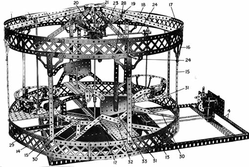
Fig.1 Gral View of Roundabout.
Pag.1
From time beyond memory the roundabut has been a source of pleasure to young people. The progress of civilisation has changed it, of course, as it has changed almost everything else, and it is difficult to recognise the huge whirling structures of to-day as the direct descendants of the creaking contraption which, at the instance of a perspiring operator, was induced to revolve slowly with its load of half-a-dozen children. Yet from this humble source have sprung all the hurtling dragon, flying boats, and similar ingenious devices with which our modern fairs are provided.
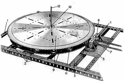
Fig.2 Base of rondabout, sowing gear roller-Bearing Unit position
Note the Pinion by which the upper Race carrying the Rondebout is rotated.
In its original form, however, with a few alterations such as increased size and the use of steam or electric power, the old favourite is as popular as ever, and it is a poor fair that does not boast an old-fashioned rondabout.
Young people who, having attained the mature age of sixteen or seventeen, are restrained by an overburdening sense of responsability from taking part in the general “fun of the fair,”often yield to the temptation to bestride a glorified quadruped bearing the somewhat fanciful inscription”Sally” or “dobbin,”and even staid old men who, if they have smiled at all during the last ten years, do not betray the fact by their faces, have been known to cast dignity to the winds and take a ride “for old time sake.”
Modern amusement devices cannot completely oust from our fairs the old-fashioned roundabout.
Young people who, having attained the mature age of sixteen or seventeen, are restrained by an overburdening sense of responsability from taking part in the general “fun of the fair,”often yield to the temptation to bestride a glorified quadruped bearing the somewhat fanciful inscription”Sally” or “Dobbin,”and even staid old men who, if they have smiled at all during the last ten years, do not betray the fact by their faces, have been known to cast dignity to the winds and take a ride “for old time sake.”
Modern amusement devices cannot completely oust from our fairs the old-fashioned roundabout.
The Meccano Roundabout is an excellent example of the adaptability of the Meccano system. The different movements, which include the rotating superstructure, the revolving cars, and the leaping horses, are all faithfully reproduced as in the prototype of the model, and its appearance when working
gives an effect of realism that can only be fully appreciated by those who have actually seen the model in operation.
The base of the roundabout (Fig. 2) is built of two 24 1/2" Angle Girders joined by nine 12 1/2" Angle Girders 1, 2, 3, 4. A 5 1/2 by 2 1/2" Flat Plate 5. bolted to the Girders 3, carries two Trunnions joined by a 2 1/2" by 1” Double Angle Strip 6, which, together with the Plate 5, provides bearings for a short Axle Rod carrying a 1" Sprocket Wheel 7 and a special toothed wheel 8.
The Roller Bearing (Fig. 2).
The large Geared Roller Bearing on which the whole of the superstructure rotates may be purchased as a complete self-contained unit (part No. 167).It is suitable for incorporation in many different models, and comprises two
large Geared Roller Races (9 in the illustration, Fig. 2), each about a foot in
diameter, a Ring Frame, sixteen 3/4 Flanged Wheels 11, sixteen Pivot Bolts
with nuts, and a special Pinion. The small Flanged Wheels are journalled
on the Pivot Bolts, which are secured round the outer edge of the Ring Frame,
and the latter is inserted between the two Roller Races
so that the Flanged Wheels run smoothly on a shoulder near the edge of the lower Race 9, which is bolted to the Girders 2, while the upper Roller
Race, by means of a similar shoulder resting on the 3/4" Flanged Wheels, revolves easily, yet steadily, about the Axle Rod 12. In this way no points in the moving surfaces are allowed to by in sliding contact wich each other; hence friction is reduced to a minimum The Ros 12 is secured rigidly in the boss of a Bush Wheel that is bolted to the lower Roller Race 9, and passes through another Bush Wheel should be removed so that the the upper Race is quite free to revolve about the Rod 12. The revolving portion of the model is built on to a base formed of eight 9 ½” Angle Girders 13 bolted to the upper Geared Race 9 of the Roller Bearing and having their outer ends secured by means of Angle
Pag.2
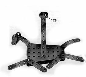 Fig.3
Fig.3
Leaping Horse detached from rondabout
Bracket to a circle formed of five 12 ½” Braced Girders and one 5 1/2" Braced Girder (Fig. 1). These Girders are all bolted end to end except the 5 ½” Girder, one end of which overlaps the adjoining 12 ½” Girder by three holes, and are joined by 9 ½” Strips 15 and Architraves 16 to a similar circle of Braced Girders 17, connected in their turn by means of the 9 1/2" Strips 18 and the 3 1/2" Strips 19 to Angle Brackets bolted to two Face Plates 20 (see figs. 1, 4). A circle com-
posed of six 5 ½” Strips 29, overlapped as required, is carried on eight vertical 2" Angle Girders bolted to the Girders 13, and is connected to the Braced Girders 14 by four 5 1/2" by 1/2" Double Angle Strips 30.
The bosses of the Face Plates 20 form journal bearings for an 11 ½” Axle Rod 21 to which is secured a Contrate Wheel 22 (Fig. 4) that engages the teeth of the four 1" Gea r Wheels 23 on the Rods 24. The Axle Rod 21 is extended by means of a Coupling 25 and the short Rod 12, which is secured in the boss of the lower Geared Race of the Roller Bearing, so that the Contrate Wheel 22 the revolving structure causes the Gear Wheels 23 to travel around the Wheel 22, at the same time rotating about their own axes and operating the jumping horses and revolving cars.
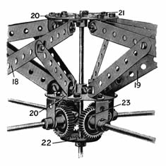 Fig.4
Fig.4
Operating Mechanisn at top of Main Stem
Leaping Horses.
The horses on ther Rondabout are no hacks:common hacks : indeed they are rather remarkable
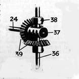 Fig.5
Fig.5
Mechanism operating Revolving Car.
Creatures and the iact that they bear only a slight general resemblance to the animals whosename they boast will, unless our experience jof roundabouts is at fault, make them all the more suitable for incorporation in'this'model. The body of each horse, as will be seen from Fig. 3, consists of a Sector Plate, and is provided with a tail (a 2 1/2" large radius Curved Strip) and four 2 1/2" Strips representing legs. The passenger is expected to sit astride the horse immediately behind the supporting Strip. During "rush hours" no doubt an extra passenger could be squeezed in between the front of the supporting Strip and the horse's neck. The gracefully archerd but rather ill-nourished neck may be distinguished from the tail by the fact thats it bears a shapely head (two 1 1/2" Strips) surmounted by a Flat Bracketwith which the poor beast must do his best to hear. Much fun may be obtained by adjusting the angles of the neck, tail, and legs to represent the characteristic trotting and galloping attitudes. Each of the horses is carried on a 5 1/2" Strip bolted to a Single Throw Eccentric 28, which, secured to one of the Rods 24, imparts a realistic leaping motion to the horse. One end of the horizontal Rod 24, on which the Eccentric 28 is mounted, is jurnalled in a 1” by 1” Angle Bracket secured to the lower the Face Plates 20, while the Braced Girders 17 and the Architraves 16 provide a bearing for the opposite end.
A 5 ½” by 2 ½” Flat Plate 31 is bolted to the Girders 14 and the strip 29 by means Angle Brackets, and caries double arm Crank 32, in the boss of wich is secured a 3” Rod 33true the longer flange
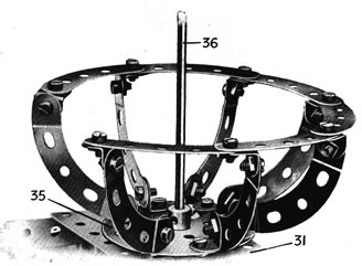 Fig.6
Fig.6
Revolving Car.
Pag.3.
Revolving Cars.
Each revolving car (Fig. 6) comprises a Face Plate 35 to which seven 2 1/2" small radius Curved Strips are affixed by means of Angle Brackets. Six 2 1/2" large radius Curved Strips attached to the
upper ends of the small radius Strips form ; rest for the occupants of the car. An 11 1/2 “ Axle Rod 36, secured in the boss of the Face Plate,is journalled in bearing consisting of the 5 ½”by 2 ½” Flat Plate 31 and AngleBracket 27 bolted to one of the 9 1/2" Strips 18. This Rod
36 passes through the central transverse hole of a Coupling 37, in the logitudinal bore of which is journalled one end of the Rod 24.
The Rod 36 is supported cupling 37 by a fixed Collar 38, and carries a second fast Collar between the Face Plate 35 and the Face Plate 31.
The Rods 24, 36 carry 3/4 Bevel Gears 39 that are in continuous engagement with each other. Thus, as the whole upper structure revolves, the 1" Gear Wheels 23,
rolling around the teeth of the Contrate Wheel 22, rotate the Axle Rods 24, and this movement, transmitted via the Bevel Gears 39 to the vertical Rods 36, causes the cars to spin round, while at the same time the horses, actuated by the Eccentrics 28, leap in the most approved roundabout fashion.
The effecto produced by the variety of motions embodied in the model . is
remarkable. For this reason the Meccano rondabout is an ideal model for attractin attention to window display or Meccano Club exhibitions, etc.
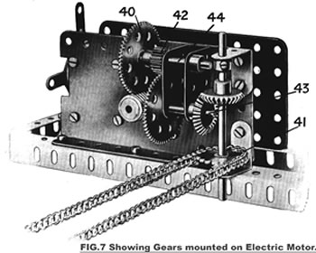
Arrangement of the Gearing.
A Worm Wheel secured to the armature spindle of the Electric Motor (see Fig. 7) meshes with a 57-teeth Gear Wheel 40 on the Rod 44, to which is also secured a ½” Pinion 42 that engages a second 57-teeth Gear Wheel on the Rod 43. The drive is then led via a pair of 7/8" Bevel Gears to a 1” Sprocket Wheel 41, which is connected by an endless Sprocket Chain to the 1" Sprocket Wheel 7 (Fig. 2). The special 1" Pinion 8 is secured to the same Rod as the Sprocket Wheel 7, and by turning the upper Geared Race of the large Roller Bearing causes the platform and superstructure of the roundabout to revolve about the Rods 12, 21.
It should be noted that the gearing just described was designed for use with the Meccano high-voltage Electric Motor, and is unsuitable for the 4-volt type. The latter is, however, quite powerful enough perate the model at a considerable speed, if it is desired to make use of the maller Motor it is only necessary to omit he 1/2" Pinion 42 and the gears on the Rod 43, adding a 7/8" Bevel Gear on the end of he Rod 44 to mesh with a similar Bevel Gear on the vertical Rod that carries the Sprocket Wheel 41. By this means the total reduction of the gearing will bediminindhe o one -third of that afforded by the original arragement The operation of the Roundabout is entirely automatic, and once the Motor has been started the model will work continuosly without any attention what ever. The realism of
itis apparence will be greatly enhanced if the roof,everfloor and central part ai All gears and bearing fillet
in irance will be greatly enhanced if the roof, n with suitably coloured cardboard. . the Roundabout should be oiled at frequent attention being paid in this respect to the Geared Roller Bearing. If this is done, the model should work almost noiselessly and without any sign of shaking or rattling. The gearing has been so arranged that the Roundabout will operate at a speed proportional to that of its prototype, but if a greater speed is required, it is only necessary to make a slight alteration to the gearing similar to that already described, as the Electric Motor has an ample reserve of power.
Those boys who possess a sufficient number of parts will doubtless be able to improvide the model considerably. For eample the revolving platform might be filled in with Flat Plates, and steps might be arranged around its sides.
LIST OF PARTS REQUIRED TO BUILD THE MECCANO RONUNDABOUT
| 17 of Nº | 1a | 62 of Nº | 12 | 1 of Nº | 26 | 2 of Nº | 54 | 2a of Nº | 100 |
| 8" " | 2 | 6 | 12a | 2 | 27a | 12 | 59 | 16 | 108 |
| 8" " | 3 | 5 | 13 | 6 | 30 | 2 | 62b | 4 | 109 |
| 8" " | 5 | 2 | 14 | 1 | 30c | 3 | 63 | 2 | 126 |
| 4" " | 6a | 1 | 15a | 4 | 31 | 5 | 70 | 4 | 126a |
| 2" " | 7 | 2 | 16 | 1 | 32 | 16 | 90 | 2 | 130 |
| 7" " | 8 | 1 | 16a | 288 | 37 | 14 | 90a | 1 | 160 |
| 8" " | 8a | 1 | 16b | 8 | 38 | 2ft.ofNº | 94 | 1 | 167 |
| 8" " | 9e | 1 | 18a | 1 | 48a | 2 | 96 | 1Electric | |
| 2" " | 10 | 2 | 24 | 8 | 48 | 10 | 99 | Motor |
Alternative Construction
If desired Meccano built-up roller bearings may be substituted for the special Geared Roller - Bearing unit. Suitable built- uproller bearings are described in the " Standar Mechanisms Manual "(detail Nº.101)If this form of construction is adopted the following
alternationns are necessary to the list of parts requiered. for part Nº167 substitute.
| 8 of Nº | 2a | 8 of Nº | 20 | 3ft.Nº | 94 |
| 8 | 3 | 76 | 37 | 2 | 109 |
| 8 | 9a | 16 | 38 | 16 | 119 |
| 16 | 12b | 8 | 48 | 8 | 125 |
| 8 | 16a | 8 | 59 |